Robotic Motor Types and Controls
by Terence Thomas
If you plan to get involved in robotics, you will need to familiarize yourself with the many types of motors
available. All robotic movement is motorized in one way or another, so it is important to know what your
options are.
DC MOTORS
Besides being battery operated, a DC motor's direction of movement is determined by the polarity of the power
input. This is an absolute necessity for robotic functions. Fortunately this type of motor comes in a wide variety
of sizes, voltage requirements, and is available everywhere. In the photo are several different types:
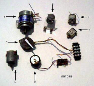
1. Mobility base motor
2. High speed hobby motor
3. Belt drive motor
4. Slot car motor
5. Pulse operated
6. Arm adapted motor
7. Bipolar stepper with pointer
Larger motors are best suited for mobility bases that allow robots to maneuver the terrain. Some of these motors
come with gearboxes to produce the slower speed and torque needed for mobility. Lowering the voltage to a motor can also
slow it down to a more desirable speed. Only experimentation can determine if your motor will operate with a
lower voltage. If it does, you’ve saved yourself a lot of trouble, if not, there are other ways of slowing down
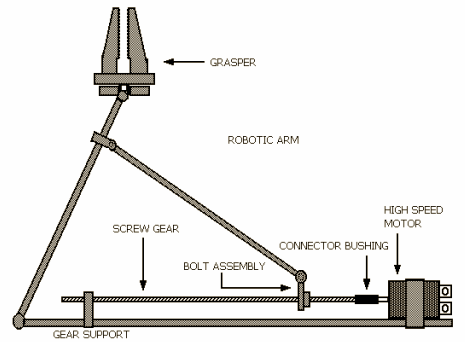
motors. Some high-speed motors can be used if worm gears or screw gears are used. An example of the screw gear
can be seen in the robotic arm illustration. When the motor turns clockwise the bolt assembly is pulled to the
motor and the arm contracts and when it turns counter clockwise, the arm extends. Although the motor shaft is
turning fast, the arm action is considerably slower because of the screw reduction.
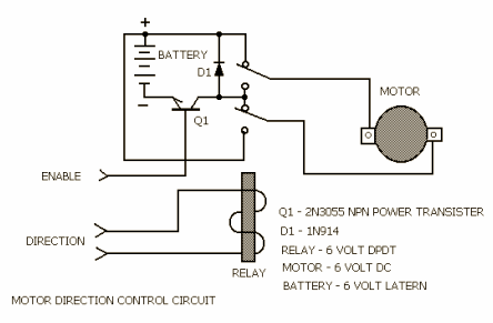
In this following motor circuit illustration, we see a DC motor controlled by a power transistor. A relay switch
(Double Pole Double Throw), determines the direction. Transistor Q1 should be a power transistor to take the
heavy load of a motor.
PULSED MOTORS
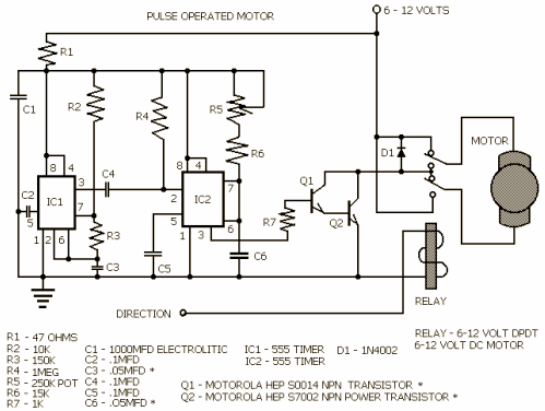
Some motors derive a speed reduction by operating from a pulsed DC signal. This signal is usually about one
hundred Hz. The speed of the motor can be altered by changing the pulse width, not by changing the frequency of
the pulse. Motors like these can be found in surplus electronics shops and can easily be identified by the pulse
generator connected to it. Any DC motor can be driven by a pulse source though, and a schematic of such a circuit
is included. As you can see a 555 timer was chosen as the drive oscillator, which produces a frequency of
approximately 100 Hz. Resistor R1, and capacitor C, stabilize and isolate the pulse generator from the spikes
produced by the motor. Since this device can draw from a power supply of 6 to 12 volts, you might want to change
the value of capacitor C4 and C6 for better results, depending on what voltage you use. The pulse output is
taken from pin three of IC1 and fed to pin two of IC2, also a 555 timer.
The second timer varies the width of the pulse by adjusting the voltage that is fed to capacitor C6 through
potentiometer R5 and resistor R6. The duration of the pulse is what determines the speed of the motor and the
pulse width can be adjusted from 10% to 100%.
Transistor Q1 receives the pulse width modulated signal through resistor R7. Since Q1 is a low current device,
it passes the signal to Q2, a power transistor that can handle the current demands of the motor. These
transistors are not critical and almost any type of low-current power transistor will work. The relay
will determine what direction the motor will take.
STEPPER MOTORS
The most complex of all motors is the stepper motor. Like the name infers, the motor turns in degree
increments and is pulse operated. The exact degree of turn per step can vary from one manufacturer or model
to another, but 20 degrees is popular and produces 18 steps for one complete turn.
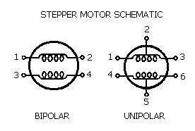
There are two basic types of stepper motors, bipolar and unipolar. As you can see in the stepper motor
schematic, the bipolar is simply a two coil operated motor. The unipolar type is two coils with center taps.
If the center taps are ignored, the unipolar motor can operate as a bipolar type. The two coils in a stepper
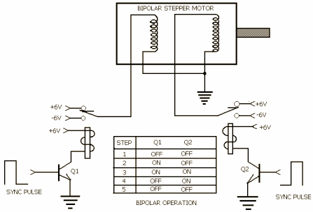
motor are fed step pulses alternately in polarity from coil to coil. A map of this process is provided in the
working diagram to graphically represent the motor action. Unlike conventional DC motors, torque decreases
with speed. A special type of drive unit is also required to advance the stepper motor and should be supplied with
the motor. It is not recommended that you build a control unit unless the motor is supplied with a good spec
sheet that has component recommendations and full schematic.
The motor may require buffers to isolate it from the drive system, or it may require a separate power supply.
Whatever the needs, they may vary considerably from one motor to another. Hobby shops are the most reliable
suppliers of stepper motors, and although surplus electronic stores may occasionally have them, they may not
include the necessary spec information
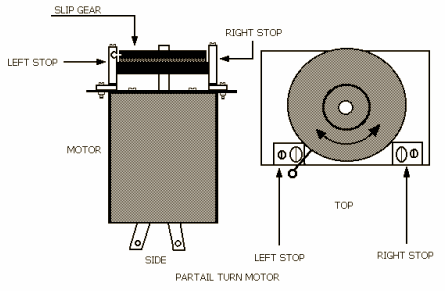
PARTIAL TURN MOTORS
Some robotic functions require only a partial turn, such as head or arm movements. The easiest way to achieve
these is with position stops and slip gears. An illustration of the mechanical details of this type of motor
is provided above. Micro-switches can be used as stop sensors to turn the power off and reset the direction
for the next action. The bottom wheel is connected to the motor while the top wheel is separated from the
bottom wheel by a circular piece of felt. When the bottom wheel turns the top wheel turns with it until the
stop pin comes in contact with the micro-switch. Some designs do not make provisions for stopping the motor,
so simple screws with spacers will function as motor stops.
HALL EFFECT AND OPTICAL MOTORS
'Hall effect' is named for its discoverer, American physicist Edwin Hall. When a conductor or semiconductor
is subjected to a magnetic field, it produces a Hall voltage. The magnetic field distorts the flow of
electrons, enabling designers to use the hall voltage to drive motors without generating sparks. The use
of Hall effect motors will enable robots to operate in hazardous situations (where explosive substances or
gas is airborne), without trigger explosions.
Another type of motor that does not produce a spark is an optical drive motor. A slotted disc on the rotor shaft
is set between two LEDs and two phototransistors, alternately passing or interrupting an infrared
beam. This creates switching signals that feed drive coils, which attract or repel a fixed magnet on the drive
shaft. This optical drive technology is in its developmental infancy currently and may become more commercially
available in the future.
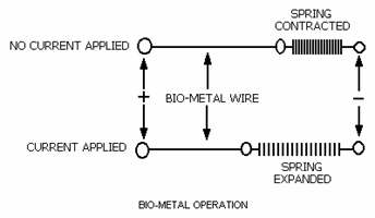
BIO-MOTOR
Bio-metal is an amazing substance that has been around for a few years and it has a number of applications
in the field of robotics. We can see in the illustration, that a piece of bio-metal wire will shrink by five
percent of its length when just a few volts are applied across it. After years of testing, bio-wire has proven
to be strong, reliable, and is becoming more useful as new products emerge. Its somewhat slower response time
makes it ideal for robotic arm and hand applications, where jerkiness would be problematic. A long piece of wire
can produce a significant movement when stretched the entire length of a robotic arm. There are robotic arm kits
currently on the commercial market that use the bio metal.
RELAYS
The relay, in robotics, is almost always used to isolate the power meant for motors, from the power supply for
computer function. Motors, because of their low impedance, make heavy current demands on power supplies and
create multiple glitches that computers can not tolerate. It is therefore a good idea to use a separate high
current source for just motors.
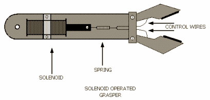
SOLENOIDS
Solenoids are best used as manipulator control devices or switch operators. Their movement is quick and
strong so a spring is almost always used in graspers to soften the action. As you can see in the illustration,
control wires are used to close the grasper. These control wires can also act as return springs. Graspers such
as this are found more in production line work where the task is very measured and covers narrow parameters.
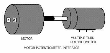
SECONDARY FUNCTION
Most motor functions involve mobility, arm, head, or some other visible external movement, however, some motor
movements are not so visible. Large industrial robots use hydraulic systems that use pump motors to produce
operating pressure of a hydraulic fluid. Another important secondary function of motors is control adjustment.
To improve accuracy, potentiometers that are interfaced with motors are usually multi-turn devices.
CONCLUSION
Robots can be very complex devices requiring a wide variety of motor-driven movements. This article is meant to
give an overview of the range of devices you may be dealing with as a robot builder. It would be a good idea to
start by doing research on robotic equipment suppliers and available supplies. There’s a vast amount of product
available now and the Internet makes it easy to find, learn about, and use. Whatever your needs, a little
ingenuity and the determination that all robot builders seem to have should serve you well. □
Terence Thomas is an educator and contributing author (t1t7t91 at yahoo.com)