DC power supplies, my mistake, and what I learned from it
Years ago, when I was working in electrical construction, one of our customers was implementing a new inventory
system in their warehouse. They wanted to install a laptop computer and barcode reader on each of the forklift
trucks to keep track of each item that was loaded or removed from the storage shelves. To avoid having to
recharge the laptop batteries every night they purchased a 12-volt adapter cord for each computer and asked if
I could connect them into the power of the electric forklifts. It wasn’t the type of work I normally did but I
agreed to give it a try.
I determined that the forklift systems were 36 volts DC, and that I would have to regulate that down to 12 volts
DC to be compatible with the adapter cords. I purchased a TO-3 style linear voltage regulator and some other
components to form a complete regulator circuit, and made sure that both the input voltage and current ratings of
the regulator were high enough to give me a reliable operating margin. I then assembled a prototype unit by
mounting the TO-3 on a large heat sink (with thermal conductive paste), connecting the other components
(fuse holder, filter cap, etc.), and putting the circuit in a ventilated enclosure. I thought I was all set with a
good solution for the customer but I made one important and embarrassing oversight – the power dissipation.
Linear voltage regulators can be very inefficient, especially when you’re dropping the voltage from 36 to 12 VDC.
They essentially work by operating as an automatically variable resistor. Within the regulator, a sensing circuit
connected to the output terminal automatically adjusts the conductivity, or resistance, of an internal power
transistor so that the output voltage equals the output rating of the device. It’s simply a matter of Ohm’s law
(V=I*R), where the current draw of the circuit multiplied by the resistance of the power transistor equals the
voltage drop between the input and output of the regulator. The main problem with this method, however, is the
equation P=E*I, where generated heat in watts (P) equals the voltage drop across the device (E) multiplied by the
current flow through it (I). For my application, every watt of power that went to the laptop computer resulted in
2 watts of waste heat generated within the regulator. Despite my ‘large’ heat sink, thermal conductive paste, and
ventilated enclosure that poor regulator cooked like a steak over a cowboy’s campfire.
As I remember, after about a week the customer called me back to tell me that the computer had stopped working.
I took apart my regulator box and some discoloration on the TO-3 device told me it had overheated. This prompted
me to do what I should have done in the first place – do some research and purchase a switch-mode DC to DC
converter. I assembled a second prototype unit using the new DC to DC converter and it tested successfully.
I built several more units for them the same way and they’ve been working without trouble ever since.
At the time my specialty was in electrical construction (wiring methods; electrical and building codes) and I
wasn’t familiar with the fundamental differences between linear and switch-mode voltage regulators. The failure of
my first prototype regulator forced me to learn some things that I thought were pretty interesting. If you’re
already an electronics engineer you most likely won’t find any of this new, but if you’re an experimenter
interested in power supplies I hope this will be somewhat helpful.
As I explained above, The basics of a linear power supply regulator are that it takes a DC voltage, that is above
the desired output, and reduces it to the output voltage level by varying the conductivity of a power transistor,
much like a rheostat. A control circuit monitors the output and adjusts the power transistor accordingly.
Switch-mode power supplies monitor output in a similar fashion, but differ greatly in the way they control the
voltage.
A power transistor ‘switches’ the incoming DC (or AC) fully ON or OFF, typically in a pattern of ‘pulse width
modulation’. Because the power transistor is either fully ON or OFF, rather than in resistive mode, there is
very little power lost, and therefore less heat generated and higher efficiency. Additionally, if a transformer
is used it can be much smaller. At 60 Hz. AC a reduction transformer must store a significant amount of power in
the form of magnetic flux in its iron core. If the transformer is fed with pulsed power of a higher frequency,
then the cycles are closer together, less power needs to be stored, and the device can be smaller and lighter in
weight. This is characteristic of switch-mode power supplies.
Examples
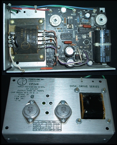
Here’s a linear regulated power supply from an older computer. “Older” as in Z80 microprocessor and floppy disk
drives. It delivers 5 VDC @ .7 amps and 12 VDC @ 1.1 amps, pretty low wattage. The transformer has multiple
secondary taps, which feed to essentially two separate regulators on the circuit board (5V left, 12V right).
With linear regulators it’s important, for the sake of heat and efficiency, to transform the voltage as close as
possible to the desired output of the power supply. That minimizes the voltage drop and wasted power across the
power transistors. As you can see from the photo, the secondary leads connect to diode rectifiers on the circuit
board. The output of the rectifiers goes to filtering capacitors. During operation they charge up with DC voltage
and deliver that voltage during the ‘dips’ from the rectifiers. Because AC power goes to zero volts twice for
each 60 Hz sine wave, the DC ‘dips’ 120 times per second from the rectifiers and would be unacceptable ‘ripple’
for most uses. The capacitors, therefore, are considered to ‘filter’ out most of that ripple. Next, the power
travels through the power transistors (TO-3 devices shown on the rear) which modulate the voltage to the
specified output by varying their resistance. They’re each controlled by one of the 14-pin regulator ICs near the
center of the board. Those ICs monitor the voltage at their respective output terminals and adjust the power
transistors accordingly. The silver disks with crosses are potentiometers for fine-tuning the output voltage.
The other components at the top of the circuit board complete the monitoring feedback to the ICs, with the
smaller capacitors cleaning up most of the remaining DC ripple.
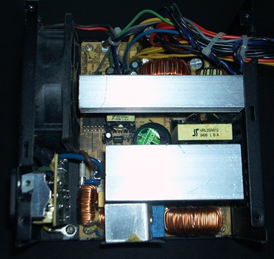
This is a modern switch-mode PC power supply. Actually it’s the one from my previous computer that I built, which
took a wicked blast from a lightning strike and kept going like a champ. I wish I could say the same for my other
electronics on that day, but that’s another story for another time. Looking at this power supply you notice that
it’s different in quite a few ways. It’s approximately the same physical size but there’s no comparison in power
capacity. This one is rated for 360 watts with 5 outputs: 3.3 VDC @ 26 amps, 5 VDC @ 30 amps, 12 VDC @ 21 amps,
-12 VDC @ .8 amps, and 5 VDCs @ 2 amps (standby). The 120 volt AC line cord connects at the bottom left and feeds
power into the circuit board without being transformed down first. A full-wave bridge rectifier (mounted beneath
the bottom-most heat sink) converts the 120 volt AC to raw DC voltage with 100% ripple. The inductors at
the bottom (round copper coils) serve a power storage function similar to a capacitor. Inductors are kind of fun
in the way they do this. The current flow through the exterior copper coil ‘induces’ a magnetic field, or flux,
into a doughnut-shaped iron core within. The energy is stored as magnetism in that core and is released in
exactly the opposite way – the collapsing magnetic field induces a current flow through the copper coil according
to Faraday's law of induction. This stored energy is drawn by the switching transistors, which are mounted
on the other two rectangular heat sinks. With switch-mode power supplies this modulation typically takes place on
the primary side of a step-down transformer. You can see this transformer sandwiched between the two large heat
sinks and marked with a yellow label. Notice how small it is, even though the supply has a high power capacity.
This is possible because of the higher power frequency, as explained earlier. The inductors above the upper heat
sink are for the switching regulators on that heat sink, and the capacitors at the top of the board filter out
most of the ripple from the outputted DC voltages. Because there are 5 outputs from this supply it makes it
difficult to give a simpler logical description, but that’s the basic idea of operation.
Learning Resources
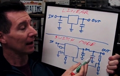
Here’s a great explanation video on the operational differences between linear and switch-mode power supplies
from an engineer. He’s like an electronics world version of Steve Irwin, but I like his enthusiasm and I think
he does a great job describing how they work. (Approx. 17 minutes)
click here
Other terms:
Full-wave bridge rectifier
Pulse width modulation
Ohm's law
Magnetic flux
Inductor
Faraday's law of induction