
| Energy in Nature | Inventors & Inventions | Workbench Fun | Physics Lab |
|
Consumer Products | Computers | Automation & Robotics | What's in the Future |
|
DCC TERMINOLOGY By Frank T. Verrico - MRC Tech Support
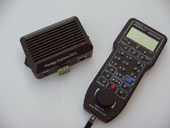
This is a simplified version of DCC terms and their meanings, written by a model railroader for other model railroaders who are entering in the field of digital command control to operate their trains. It is by no means meant for people who hold a PHD in electronic engineering or geek speak. It is meant for a person that may consider that this is geek speak, but all it is, is a basic introduction to the world of DCC A newbie to DCC will need to know some of these terms to understand what people are talking about at the next club meeting. DCC - a.k.a. Digital Command Control - A model railroad/train control system, that uses special chips, known as decoders, inside locomotives, rolling stock or trackside, that receive digital packets of information and commands from the DCC System. This system of train control allows the use of multiple locomotives/trains on the same stretch of track at the same time. The digital packet signal is piggy-backed onto an a.c. sine wave that powers the track. This type of train control system should not be confused with "carrier command control", or "R.F., [radio frequency control]", as they can not be inter-mixed and are not compatible with each other. Although some DCC system manufacturers do make radio controlled throttles for their specific systems. DCC System - The basic system is usually comprised of a power supply, Base Unit or Base Station, and a control center keypad/throttle, which can be fixed to the base station or can be an individual walk around handheld, commonly called a cab, [like cab of a locomotive]. The power supply powers the base station, and it’s control center, along with the track rails which in turn powers the trains. The base station receives commands from the control center then sends a digital packet of information to the specific decoder the operator wants to control via the decoders address. The DCC System can also [re-] program the decoder to set it’s parameters. Decoder - A circuit board comprised of electronic components, that basically make it a micro-processor. Each decoder is assigned, [by the DCC System], a unique individual address, that lets it receive only the information, [digital packet], sent by the base station to it and not any of the other decoders on the track rails. Each decoder contains a certain amount of CV’s built into it, that disseminates the information received to control specific functions that the decoder must perform, eg: direction, lights, speed, etc. There are usually 2 types of decoders:
Address - A unique, individual, i.d. number assigned to a specific decoder. There are 2 types of addresses:
Most decoders come with a factory default address of #3. This is so an end user can run a locomotive/decoder right out of the box, without any programming to perform, or guessing as to what address the locomotive/decoder actually is. CV’s - a.k.a. Configuration Variables - These are folders built into the decoder which contain the information for each specific function of the decoder, [address, lights, etc.]. Each CV can be [re-] programmed by the D.C.C. System, to custom tailor that specific function. For example; CV #1 contains the information of the 2 digit address assigned or programmed into the decoder. By programming a certain variable, [number], into a CV tells that CV what to perform in that decoder. CV’s are also referred to as Registers, although some times registers numbers do not coincide with CV numbers, for example register #5 = CV #29. *NOTE: CV #29 is known as the Configuration Data CV As CV’s go, this is the brains of the decoder. Inputting erroneous data into this CV can put the decoder to sleep. Be aware of your programming prowess before playing with this CV.
Programming - Every DCC System has the capability to input data, [program], into a specific decoder and it’s specific CV’s. This is done through the base station via the keypad control center. Programming can be done on a dedicated program track or if the decoder is made for it, programming on the main track, [ops mode programming]. Program Track - A dedicated, isolated piece of track used to program data into a decoder. It is isolated as not to program that same data into every decoder on the layout. Programming on the program track is also called, Service Mode Programming. Test Track - An isolated section of track fitted with a resistor in line to one of the leads, to test the installation of a decoder in a locomotive or piece of rolling stock. The resistor limits full current going to the decoder to protect it from being burnt out if the installation is not done correctly. Programming on the Main, [track]- a.k.a. "OPS MODE PROGRAMMING" - If the decoder has this feature built into it, and the DCC System has this capability, after you initially program the decoder on a program track, you can change it’s parameters while it is on the mainline, without having to physically remove it from the layout. No matter what, you need to know the decoders address to do this feature!! Functions - Additional controllable features, [lights and/or sounds], built into a decoder that is accessed via the control center’s function buttons. The amount of functions built into a decoder depends on the manufacturer, and the amount of functions that can be controlled by a DCC System also is dependant on the manufacturer of the DCC System. Functions and their associated function buttons are normally referred to as for example; F0 or Function Zero, which turns on the directional lights of a mobile decoder, and on up to the maximum amount of functions. Presently the N.M.R.A. has certain function numbers assigned for certain functions, while other function numbers are up to the decoder manufacturers discretion. Each function has an associated C.V. or CV’s that can be programmed to custom tailor that function. The Control Center or Throttle will have a numeric keypad associated with the function numbers, so the functions can be activated. Function Re-mapping or Re-mapping - Certain CV’s and their associated functions can be moved around inside a decoder, to either change it’s function button assignment or to group a number of functions together so that a press of one function button activates multiple functions at the same time. This is not true of all decoders, this feature is optional by the decoder manufacturer. N.M.R.A. - National Model Railroad Association- Presently there is a D.C.C. working group within the N.M.R.A. that puts out a list of R.P.’s, [Recommended Practices], that are used as guidelines for DCC System and decoder manufacturers, to insure inter-manufacturer compatibility between products. You can visit their website - www.nmra.org to view these R.P.’s, and other related information. This group specifies that certain numbered CV’s are present in a decoder for inter-manufacturer compatibility. The rest are optional and can be used for other purposes by a decoder manufacturer. Digital Boosters - These units amplify track voltage and the DCC signal, and also increase the power output of your DCC system. If you have a large layout and operate numerous trains on the layout you would most likely need some type of digital booster. Digital boosters are specially designed for DCC, and you can not use a regular analog power pack as a DCC digital booster. Power Districts - Large layouts that use numerous trains should be electrically divided into isolated, [electrically], power districts. A digital booster should be used for each district in conjunction with the DCC system base unit to evenly supply power throughout the whole layout, and make troubleshooting electrical problems easier to find. Busses - There are two types normally referred to:
Reverse Loop or Reverse Section - This is a section of the track rails that fold back upon itself allowing a train to travel upon the same trackage in the opposite direction from which it came. Both ends of the reverse sections have to electrically isolated from the rest of the layout with insulated, [plastic], rail joiners, and special wiring practices are needed for this section of track to avoid short circuits. A turntable bridge is also considered a reverse section. Reverse Loop or Reverse Section Controller - This is a piece of DCC system equipment , [MRC #AD520- Auto Reverse Loop Controller], that makes wiring a reverse loop or reverse section of track easier, with no buttons to push or toggle switches to operate as the train traverses the reverse section. Only the Controller feeds electricity into the loop or section, do not feed power into this section by any other means. Speed Steps - Speed steps are incremental steps on the throttle and programmed into the decoder that go from speed zero to full speed. Presently there are three groups of speed steps that you can use, 14, 28, or 128. For example, if your decoder is programmed for 14 speed steps, your throttle and decoder will go from stop to full speed in 14 clicks/turns of the throttle. Older decoders were made with just 14 speed steps, while newer decoders can hold all three, and the end user can pick which group they want in a certain decoder. 128 speed steps gives you a finer throttle control. Also most DCC systems allow you to set your throttle to match the decoders programmed speed steps so throttle and decoder are in sync, while some DCC systems automatically program a decoder to a pre-set speed step and only allow running on the systems speed step without the ability to pick your own or change it. If you want to impress someone, you can tell them that speed step 128 uses Bit 7 for direction, then you divide the top voltage by 127, [the remaining bits 0 to 6], then speed step 1 is equal to that voltage, and speed step 2 is equal to two times that voltage, etc., etc. Start Voltage - [CV#2] - Allows you to custom tailor the decoder to a specific point on your throttle where the locomotive starts to move. Momentum - Mimics the way real trains start and stop due to the load they are pulling. By being able to adjust this feature allows you to simulate the conditions of the train you are currently using. There are 2 types of momentum:
Top Voltage - [CV#5] - Limits the top speed of the decoder. Mid Voltage - [CV#6] - Allows the user to custom tailor the mid range voltage of the decoder into a linear or non-linear speed curve. Extended Address - [CV#17/CV#18] - The extended address of a decoder is the four digit address, [128-9,999]. The 2 parts of the extended address are placed into CV’s 17 and 18, and depending on the DCC system, might need to be inputted as a hexadecimal conversion. Consists - If more than one locomotive is assigned to pull a train, the lashing of these locomotives together is commonly referred to as a consist, a lash up, or a multiple unit, [M.U.’ed]. In DCC parlance it is simply called a consist. There are 2 types of consists present in today's world of DCC:
Stack or Re-Call Stack - Some DCC throttles or systems allow you to store a number of addresses frequently used in the system memory or throttles memory. This group of addresses is known as your stack. The DCC system will then allow you to toggle back and forth between these addresses, so you can easily recall these addresses to run, or activate their functions during a session. Some systems also allow a certain amount of addresses in your stack to be saved during a power off situation. Routes or Routing - When using turnouts with their associated switch motors and accessory decoders. Some DCC Systems allow you to program a number of turnouts to throw their points in pre-programmed directions, simultaneously, as guide the train over a certain path with the push of just one or two buttons. This is known as a route. A route can be simply considered a "consist" of turnouts. Contents courtesy of MRC™ (Model Rectifier Corporation) |
Home
|
About Us
|
Advertise
|
Submit an Article
|
Submit a Link
|
Contact Us
Copyright © 2006 electricalfun.com - All rights reserved